Microcontrollers with mid-sized touch-screen displays
- terrycornall
- May 6, 2023
- 22 min read

Updated: Feb 8, 2025
Despite owning a growing list of excellent hand-held/wearable GPSs I've been nibbling away at the task of making a home-brew outdoors navigational device for a while now, because they have their limitations. Battery power and readable screens being two, doing stupid things like hiding huts and tracks at various inconvenient zoom levels being another.
Over 3 or 4 years, I've made 4 prototypes with varying success. The first used tricolor e-ink but I found that the small, slow display with 15 second refresh and no fast refresh (only monochrome eink has that) was a show-stopper. Only red and black made it hard to draw water as well as tracks and waypoints and a position icon too. The second used a transflective monochrome low-power graphical display that has great resolution and fast refresh but I found that the lack of color made it hard to use as a mapping device. Hard to tell the tracks and creeks apart, for example. I could use a blinking position icon, but how to do waypoints, for example? Couldn't find a color transflective of a suitable size either, despite them being common in smartwatches and hand-held GPSs.

For the first two attempts, it was the sunlight/blizzard/whiteout readable low-power displays that were the focus but their limitations proved too great. Also the microcontrollers I chose to use, again low-power devices, proved hard to work with because of memory limitations.
I've tried also AMOLED and TFT displays (despite them being somewhat power hungry by comparison) coupled with ESP32 S3 and S2 MCUs which have better than usual memory sizes and are quite fast, with great power-saving sleep and lots if interfacing options for GPS and compass modules.
In past 4 years, the quality and utility and functionality of the Garmin Fenix series watches (of which I have the 5x and the 7x) have improved to overcome many of the irritations that prompted me to want to roll-my-own in the first place, but small screen size and hence lack of map detail is kind of inherent in their design, plus I couldn't do a lot to affect their mapping. So I decided to see what I could do if I let up a little on the low-power requirements and went for bigger and better mcu and lcd plus threw in the requirement for a touch screen. I realise that this is taking me dangerously close to the point where a smartphone with a navigational app would do a better job than any hardware I could come up with, but still, the ability to be able to freely program it without all the Android OS getting in the way is still attractive. Plus I find that the nav apps on my Pixel 5, although good in many ways, have the very annoying feature of leaving important things off the map until you zoom in on them, sometimes needing to zoom in a LONG way before they pop up. In other words, you need to know where a hut is so that you can zoom in on it before you can see it on the map. Duh?
OK, so search for the hut, I hear you say. Uh huh. I tried that. "Google Maps, find Dorich's hut". It found one in New Hampshire USA whereas the hut I wanted, a mere 3 km from where I was, in Australia was actually called Derscho's hut, but that never came up in the search's list of possible matches to choose from until I at least got the first 3 letters correct. Do I need to remember the exact name of the hut, whilst in a brain-fog, slowly dying from standing in a freezing blizzard, in order to find it? I don't care what it is called, just show me the freaking huts on the map! You get the idea. My priorities are slightly different from Google Map's developers.
Get a better app, you say, like Alltrails, that does show the huts at all zoom levels. Uhuh, have you found one? Alltrails isn't much better than Google maps in this respect. Neither is Garmin Explore or Garmin Earthmate. It's like they don't want to put huts on their maps in case they disappear, leaving hikers in a precarious position. Fair enough, the huts do burn down occasionally.
Take a paper map then, after making sure all the huts are marked, maybe manually mark them yourself. I have considered this. It would be fun to take the available mapping databases (Like JSON or GEOJSON formatted OSM and Australian Digital Elevation Map data available from the Aussie Gubmint) and write some code to extract the important details (like huts) and leave out the crap (like who modified the position of the hut last and which administrative authority's area it is in) and then just code up some Scalable Vector Graphics output in Python to draw a nice clean map and print it and laminate it. Low power, (none required), big A4 size, sunlight readable, lightweight, has the details I want, can be referred to the GPS position using printed grids, what is wrong with that?
All I can say, in weak defense of still wanting an electronic device, is that it is all too easy to make a mistake transferring GPS coords to grids on a map to locate yourself. Especially in that brain-freezing scenario I mentioned. Out by one grid means about 1km error. Get your Eastings and Northings mixed up and you might be on another continent. OK, OK, it's not that hard to get it right, but it's not that hard to slip up either.
How about manually put waypoints into your GPS on the huts? Yeah, I do that, but sometimes I forget, or leave an important hut out...
(I have since worked out how to make a transparent Garmin compatible map using mkgmap with the huts using icons that don't disappear until you zoom way out that I've loaded to my Fenix, so that's something)
Anyway, I am an electronics engineer, dang it. I reckon I can design and program up a good device to my own specs and being retired I have nothing much else better to do most of the time (though 4 years already passed makes it obvious I am not trying too hard here) Having ranted that, I am not in the mood to deal with all the fiddly details of the hardware and circuitboards until I have a proven design so I hope that I can get some hobbyist-level kit for prototyping. So here is a list of the contenders that I have found with their vital statistics.
Needs and wants
Must haves are:
3.5" or 4" color display with touchscreens. Resistive or capacitive. (Resistive is better with big heavy gloves on... remember that blizzard...)
OR buttons/wheels that respect the use of the aforementioned chonky gloves.
16 Mbytes of flash, 8 Mbytes of ram (Or more if I can get it. Maps can be BIG)
SD card (though I can easily add one if an SPI interface is available)
ISP bus for display/SD/other stuff
I2C or UART for connecting GPS and or electronic compass module
battery power management and able to run off single LiPo
powerful microcontroller. e.g. ARM M4 or ESP32 S3 (thoughthe need for Wifi and bluetooth is moot)
programmable in C/C++ or Python or Micropython or Circuitpython.
I'd prefer transflective display or OLED but will consider backlit LCD even though more power hungry. E-Ink with at least 5 colors and a fast refresh (2 secs) or partial refresh would be nice but I'm still waiting...
WiFi and Bluetooth not needed but if they are there and can be turned off that's OK. I can imagine using them for map and GPX downloads.
Current draw when GPS on and display running but wifi, ble etc off, 100mA max for MCU and about that again for display.... Current when in deep sleep and display GPS, off, less than 100 uA.
Candidates
Unexpected maker FeatherS3 - ESP32-S3 — Unexpected Maker (This is an Aussie manufacturer! Note that this is not the Adafruit Feather S3 which doesn't have the second switchable LDO regulator for powering peripherals off during sleep.) I bought one each of the S3 and S2 because I suspect the S2 uses less current, being only single core (apart from the low power RISC-V core that I can use to monitor GPS or drive backlight PWM)
Lilygo TDisplay S3 1.9" oled+ ESP32s3 LILYGO® T-Display-S3 AMOLED ESP32-S3 1.9 inch RM67162 Display Development Board OLED WIFI Bluetooth 5.0 Wireless Module Sale - Banggood Australia
Lilygo T4 S3 2.41" oled+ESP32s3+touch T4 S3 – LILYGO®
Color OLED displays suitable for Parallel or SPI interface seem restricted to 128x128 or less. There are 5" HDMI capable with touch screen though! But I don't want HDMI.
Manu | Model | Display | MCU | Touch | Power | Battery | IO | SD | Program | Weight | Memory |
Makerfabs | ESP32-S3 Parallel TFT with Touch. 3.5" | TFT parallel connection | ESP32-S3 | Cap | | NO! | 1xI2C, 1xGPIO | Y | Arduino IDE | 52g | 16MB Flash, 2MB PSRAM |
Elecrow | ESP32 3.5" Terminal | 320x480 TFT 16 bit parallel connection | ESP32-S3 | Cap | Rated at 5v 500mA Dunno about deep sleep | Yes. Type C USB can run and charge at same time | 4x 4pin 'crowtail' connectors. Analog, Digital, UART and I2C | Y | VS Code, ESP-IDF and Arduino IDE. LVGL and Python/Micropython | 85g inc case but not battery | 16MB Flas 8MB PSRAM |
Unexpected Maker | Pro ESPS2 and ESPS3 Feather (Pro has debug header so might be better with JLINK but non pro has USB JTAG debug...) | No, but I could add one, either SPI or Parallel. Perhaps an OLED? | ESP32-S3 or S2 | | S3 uses 40mA from battery when running a 'rainbow neopixel' demo. Most will be LED!. Deep Sleep is order of 100uA. S2 might be lower power than S3 because single core. And doesn't include display | Y | STEMMA + 21 GPIO | | Arduino IDE, Circuitpython, ESP-IDF, Micropython | | 16MB Flash 8MB PSRAM |
Touch down | | | | | | | | | | | |
WT32-SC01 | | | | | | | | | | | |
LilyGO | LilyGo esp32_s3 oled | AMOLED 240 X RGB X 536(H) | ESP32-S3 | no... | | Yes | | | | | |
LilyGO | T4 S3 | Amoled 450x600 | ESP32S3 | yes cap | | yes | SPI, UART, I2C | Y | Arduino IDE, Circuitpython, ESP-IDF, Micropython | | 16M flash 8M psram |
What have I done?!
Because of the switchable LDO regulators on the board to allow easier turning off stuff in deep sleep, I went for an ESP32-S2/3 based FeatherS2 or S3 from Unexpected Maker (got one of each so I can see which is less power-hungry) coupled with a 3.5" TFT LCD Fafeicy TFT LCD, LCD Module TFT Touch Screen Display, 4-Wire Serial Peripheral Interface ILI9488 HD : Amazon.com.au: Computers the touch controller is apparently XPT2046 and it may be wise not to connect MISO (output from the display) as one reviewer claims it isn't needed and stops the SPI for other devices. Hmm. Oh, and it has SD card holder and SPI interface as well.
Unexpected Maker Feathers3
First light
So I got one and ran it up and it only pulls 40mA when running the installed rainbow led demo. When I reprogrammed it via Arduino esp code and turned the clock down from 240 to 10 and turned off the neopixel and just blinked the blue led I got it down to 14mA. (At 240Mhz it pulled 34mA so significant saving)
BTW, to get it back to Circuitpython, there's a UF2 re-installer on Unexpected Maker FeatherS3 Download (circuitpython.org)
I'm waiting for the 320 480 TFT display but I might test it with the small 128x128 OLED display just to get going.
Broken bits
If you set the cpu clock lower than 80MHz it will mess with the baud rate of the serial output setCpuFrequencyMhz() changes Serial bauds if frequency<80Mhz · Issue #6032 · espressif/arduino-esp32 · GitHub
The Arduino IDE issues a rst after programming but the rom-mask on the s3 is busted and so the reset doesn't work. Have to reset by hand. Dunno if it affects the s2 but probably not.
Helpful...
Get via library manager the UMS3 Helper by Unexpected Maker and then you can do stuff with the helper functions:
#include <UMS3.h>
UMS3 ums3;
void setup(){
  ums3.begin();   //init feathers3 peripherals
  Serial.begin(9600);
  ums3.setLDO2Power(false); //turns off (or on if true) the LDO2 regulator to unpower things connected to it

}

void loop(){
  float ls;
  ls=ums3.getLightSensorVoltage(); //reads a light sensor and gives a float tween 0 and 3.3 (A very bright light shone on it gave 1.4..... so 3.3 must be a VERY bright light
  Serial.println(ls);
  delay(1000);
}
ESP32_S3 +128x128 OLED+SD card
I had an OLED panel that I got from Jaycar, made by Freetronics (but no longer stocked and currently not available from Freetronics.com.au either) that uses a SSD1351 controller. Here's a link to schematics and wiring and so-on.
It doesn't have a touch screen, but I can play with it to get the SPI working whilst I wait for the TFT/touch that I ordered to turn up. Note that it can be powered from 5v or 3.3v. There is an onboard regulator that cuts 5v down if needed. (I found that using 3.3v also affects the brightness)
I used the Adafruit_ssd1351 library downloaded by Library Manager in Arduino IDE. (I also used TFT_eSPI in a different test)
As I am using it with the ESP32 UM feathers3, the wiring won't be quite the same, the SPI pins and GPIO pins used will be different but the code is based on an example from the Adafruit_ssd1351 library. Unfortunately, it didn't work... Compiled OK and appeared to run but nothing showed on the OLED. Also couldn't get the SD card on the oled board to work. (probably a miswiring as I got it to work after rewiring)
I tested the SPI to SD with a separate SD adapter. (I can make one with a micro-sd adapter holder easily enough. Turns out the sd card has all the smarts aboard for SPI.) This worked OK. (I did find that I have to explicitly turn LDO2 on else it may be off if I run usm3.begin() to initialise the feathers3 helper routines.)
I also tested the oled with a different microcontroller, (Mega 2560) and that worked. Which leads me to believe that I have some issue with the SPI, short of complete failure, that stops the oled working with the feathers3.
So I rewired the oled to the feathers3. Here are the wiring pinouts for the feathers3 and oled128.


In addition to the standard SCK, MISO, MOSI connections, the other pins are:
oled DnC 14
oled nCS 5 //default spi cs
oled nRST 12
SD nCS 6
Now, I have made some progress, after I tried using TFT_eSPI libraries instead of the Adafruit_SSD1351. I had to modify the user setup files
C:\Users\terry\Documents\Arduino\libraries\TFT_eSPI\Setup202_SSD1351_128.h to set the pins to the settings I want in the #define ESP32 section. And User_Setup_Select.h in same directory is modified to choose that header file rather than the default User_Setup.h. Then using the example color_test code from the TFT_eSPI library I found that it did indeed work but was so dim that I could barely see it. If not using 5V instead of 3.3V power to the oled I couldn't see it at all. Yet I know that it is usually quite bright (and tested it again with old mega2560 and old code to make sure the oled still works), so there is still something wrong with the feathers3 code. It's in D:\arduino\my_projects\esp32\oled_TFT_espi
I looed at the datasheet for the ssd1351 at SSD1351 Datasheet by Adafruit Industries LLC | Digi-Key Electronics (digikey.co.il) and checked the codes used in the init sequence (C:\Users\terry\Documents\Arduino\libraries\TFT_eSPI\TFT_Drivers\SSD1351_Init.h) and they look ok (I was checking for low contrast or brightness settings but the ones used look OK) So I am currently at a loss. I did find out how to reduce the brightness tho so that might be useful one day...
Once I noticed that the TFT_eSPI code 'worked' for the oled I went back and tried the Adafruit_SSD1351 code and it worked too, though it too needed the 5V supply to see anything and the oled was still extremely dim. I think it gets better as the supply gets higher. (I measured the +5v out of the feathers3 at it is quite low, e.g. 4.7V depending on the USB that I use. If I power from a battery it is only 3.2V or whatever. The 5V isn't really 5V.... it's the usb volts minus a Schottky diode drop, and if no USB it might be nuffin. However, it gives a nice bright display when used on the mega2560 and it has a '5v' supply that also comes in at 4.7V so it isn't just the supply voltage. (I actually tested the mega2560 voltage supply with the oled but coded and driven by the feathers3 and the mega2560 power didn't solve the brighness.) I need to look into what FTOLED library does during setup that the TFT_eSPI isn't to find a s/w fix that boosts the brightness.
At least I know the SPI is working, sorta. The SD card mounts too, now, even if I use 3.3V supply.
Comparing FTOLED to TFT_eSPI...
I went through both code's init stuff and tested a lot of things that looked a little different but they were essentially the same and the tests didn't reveal any startling things to do with brightness. (I missed the setting of GPIO0 to turn on the boost converter. See below.)
lcdgfx library
I tested this library and got example code 'working' but again the brightness is very low. There's something about the feathers3 SPI, or timing of operations or or, I dunno but something! (Ooh, there's a thought! Can I slow down the feathers3? I think I can!)
Hurts my mo to go so slow...
The feathers3 clock can be set quite low by ... setCpuFrequencyMhz() Though don't go below 80 if you still want serial baud rates to be accurate. Even going as low as 10 MHz didn't help brightness. (but see below about the fix and low freq power tests)
oops, is my face red...
I thought I had the color values specified in 2 bytes not 3 so they were all very low values.... but no, it's 16 bit RGB565 so it's all good. Red is F800 like I had specified. That's not the problem.
I find the brightness problem and get a boost...
I found it. A comment in the FTOLED initialisation code revealed that the Freetronics 128oled has the GPIO 0 bit from the ssd1351 turn on and off the boost converter that generates the higher voltages the oleds need. Display is nice and bright now, even powered from 3.3V
  //in TFT_eSPI library this is how you fix the dim display problem
  oled.writecommand(0xB5);
  oled.writedata(3); //turn on the boost by setting oled's GPIO0 to high! Why 3 not 1? Dunno but 3 works and 1 didin't
  oled.enableDisplay(); //this doesn't set the gpio0 bit so need previous
In code using the Adafrui_ssd1351 library, you need to do this differently. I fixed it for now by editing Adafruit_SSD1351.cpp and in the static const uint8_t PROGMEM initList[] in the SSD1351_CMD_SETGPIO part I changed the value 0x00 that is written to the GPIO0 to 3 ( which means set it to an output and make it high. The original 0 means set it low. 1 or 2 sets it to an input)
     static const uint8_t PROGMEM initList[] {
     .......
     SSD1351_CMD_SETGPIO, //the command to send
    1, //num of data bytes to follow
    3,   //this is what it should be to set GPIO0 high and turn on boost converter. TC
    //0x00, //this is what it used to be
    .........
     }
Currently the situation is....
As a measure of how much current the feathers3+oled use, I get 50mA total when the oled is doing a simple scrolling white ball on black screen demo, with feathers3 at 240 MHz. Only about 0.02 (1/50) of the screen is lit.
With the oled (and all of LDO2) off, I get about 40mA out of the battery if the cpu freq is 240 MHz. So Oled is only using about 10. (It depends on how much oled is lit up.)
When I slowed the cpu to 10MHz and repeated, I now draw 24mA when all is on (less than when the cpu was running faster) and 14 mA when the LDO2 (and hence the oled) is off.
The table below shows that there is a big advantage to slowing the cpu down from 240 to 10, whether the oled is off or on, but not much going from 240 to 100. It will depend on whether speed is needed for computation, drawing, file loading or whatever. Trade the time it can be asleep against the time it needs to do something. Bit like my lifestyle.
MHz | LDO2 on | mA |
240 | Y | 55 |
240 | N | 40 |
100 | Y | 54 |
100 | N | 42 |
10 | Y | 24 |
10 | N | 14 |
I did a bunch of tests where I left the scrolling display running overnight and found that at 240MHz a 1000mAh single cell Lipo battery could keep it going for about 6 hours.
I also found that the battery could be discharged very low, lower than I like, so I put in some code into the loop() that went into deepsleep if the battery got below 3.2V. It's a bit conservative, could maybe go lower, but I think the esp32s3 might be a bit unstable any lower.
//here's the battery monitor code
v_bat = ums3.getBatteryVoltage(); //needs something to stop over-discharging the battery!
  if(v_bat<3.2){ //too low
    esp_deep_sleep_start(); //go to sleep and only wake on reset

  }else if(v_bat<3.5){ //low
    oled.setCursor(30,0);
    oled.setTextColor(RED, BLACK);
    oled.print("Low");
    oled.setTextColor(WHITE, BLACK);
  }
I also did the same test with the cpu clock dropped to 10MHz and also with the brightness at full, or 1/4 levels. I found that the display brightness made a small difference but that the 10MHz clock made the major difference and would probably allow it to keep running for about 24 hrs or more. (Battery voltage dropped about 0.2V per 6 hours so from 4.2 to 3.2 is about 30 hours, assuming linear drop, which it isn't so I'll have to test it fully one (or three) days).
Keep in mind that the test was furiously writing to the display as fast as it could, all the time. A real-life scenario would be different and in fact would be characterised by long periods of inactivity whilst I puffed up a hill not needing to check the map or have the gps on. This all bodes well for the color oled display and the esp32s3 being usable for a gps hiking tool (tho I'd like a bigger one...). The GPS pulls quite a bit of current though, 30mA at least. I'll test the esp32s2 sometime, as it should have even lower current, being only single core compared to the esp32s3 two cores, one of which I am not using. Hmmm, I wonder if I can put just one core to deepsleep? Probably not as deepsleep on the UM feathers3 also turns off regulators and things.
Core, blimey
So, the esp32_s3 has two main cores (plus a low-powered one that gets programmed by assembly language). I'll play with running the battery monitor on one core and the display code on the other. It's overkill, but interesting to see if I can make it work. In reality, I don't need two cores, I don't think.
TaskHandle_t batteryMonitorTask; //for a task to run on core 0 to monitor the battery void setup(){
.....
xTaskCreatePinnedToCore(batteryMonitor,"batteryMonitor",1000, NULL, 0, &batteryMonitorTask,1); //playing with tasks .....
} ......
//this will be set to run on core 1 and enter deepsleep (which affects the entire device) //if the battery gets too low. void batteryMonitor(void * dummy) { //needs a dummy even though we are passing NULL float v_bat; //do I need to set this core freq too? for(;;) { v_bat = ums3.getBatteryVoltage(); //needs something to stop over-discharging the battery! if(v_bat<3.2){ //too low, ( esp_deep_sleep_start(); //so go to sleep and only wake on reset } delay(100); //no need to go too fast } }
Testing in sunlight
I tested the oled in sunlight and at the time it was too dim. I realised later that I could have cranked up the brightness (and hence the current...) I haven't tested it since.
Rekindle my love of the Kindle
It has occurred to me in the past that jail-breaking my Gen 3 Kindle and running Linux on it would give me access to a nice, big, lightweight, snappy grayscale display, with a (slightly klunky but built-in) keyboard and cursorpad with a familiar and powerful Linux OS behind it plus WiFi and quite a lot of memory. I haven't done this for a number of reasons:
I use(d) the Kindle as an e-reader a lot and didn't want to break it.
Tests done transferring PDF and JPEG maps to the Kindle weren't that promising. Loading speed was good, detail and res were OK but zoom and pan were slow.
It wasn't color. I like color. Does have 16 grayscales though and a big enough screen that line-thickness can be used to effect. Does have partial refresh too.
However, things have changed. I use a headphone a lot with the Kindle and it suddenly stopped working and the problem is not easily fixable (I looked and it isn't just a dodgy connector) so I stole my wife's Kindle to replace mine as she wasn't using it. This means I have a perfectly good (sans headphone but still with speaker audio) spare that I can experiment on, bwah ha ha!
OK, I tried that and it (eventually) worked but I made the mistake of doing a 'shutdown -h now' command and it wiped out all my jailbreak and usbnet stuff so I'll have to do it again. I'd still need to go into how to use the screen (bufferio I think) and how to connect the hw serial (I think it has one) to the GPS. Anyway here's my notes on the test:
I used notes from https://wiki.mobileread.com/wiki/Kindle_Screen_Saver_Hack_for_all_2.x_and_3.x_Kindles#google_vignette
and
https://www.mobileread.com/forums/showthread.php?t=272170

NOTE: You can turn off the Kindle using the 'hold slider right for 8 secs' method
BUT if you are silly enough to run 'shutdown -h now' on the kindle via a ssh shell
then it will undo all the stuff you do below and you'll have to go thru it again.
You can find the files in the uninstallers dir. Similarly if you let the battery go flat.

After doing update on the usbNetwork file you copied to the Kindle, eject and unplug it
 and then wait for it to stop spinning its cursor.
You'll need to be in debug mode to run private commands, so, on the Home screen, bring up the
search bar (by hitting [DEL] on devices with a keyboard, or the keyboard key on a K4, for example), and enter:

;debugOn

* And now we can enable usbnet:

~usbNetwork

* Your Kindle should now be detected as something like a RNDIS/Ethernet Gadget or CDC Ethernet Device network adapter. (It wasn't until I installed RNDIS hack on the PC below)

* If you don't need to enter any more private commands, switch debug off.

;debugOff

Then plug kindle back into USB on PC and nore that it doesn't appear as a disk drive.
(I'm guessing to turn off usbNetwork you do the above again. Hopefully '~' means toggle.)

USBnetwork
Then see if a new serial device has appeared in deviceManager (this is on WindowsPC )
It does, on USB serial on COM9 but I can't open a serial session to it on any baud rate.
Opening that port in device manager says its baud rate is 9600 but that doesn't work.
I tried to open a serial terminal to it using MobaXterm but it said it couldn't configure it.
I checked in the device manager Network adapters and i don't see any unidentified network
that might be the kindle (and nothing changed when I removed it from USB) so
I think I need to do ethernet over USB with RNDIS driver. https://www.mobileread.com/forums/showthread.php?t=272170
and then use device manager to update the com9 driver and assign an ip address. Did that and
now I see Kindle USB RNDIS device in devicemanager->network adapters.
Gave THE ADAPTER (not the kindle) an IP of 192.168.2.1 using:
 pc->settings->network adapters->ethernet->change adapter options->ethernet3 (kindle..)
->properties->ip4->properties->gave it 192.168.2.1 and mask 255.255.255.0

Now I can ping 192.168.2.1 (this is the interface on the PC)
and I can ping 192.168.2.2 (this is what the kindle thinks it is)
Using a mobaxterm bash terminal session I tried:
ssh root@192.168.2.2  and just return when asked for password and I'm in!!!!

Wifi network
From a console running on the Kindle (see section above) I can run:
ifconfig -a and it shows wlan0  (after I turned on the wifi in the kindle menu)
I can ping google.com for example, so it is network connected.
I could do apt get installations now! (Have to make root writable though... mntroot rw?)

Uninstallers
I put the uninstallers in /mnt/us/uninstallers using something like:
scp Update_jailbreak_0.13.N_k3g_uninstall.bin root@192.168.2.2:/mnt/us/uninstallers/

Disconnecting:
Even when the kindle is supposedly off (i.e. slide right for 8 seconds and screen goes blank)
The ssh session from the PC still stays on. Wierd. And I can plug in the usb and re-establish
the ssh even without turning the Kindle on. Obviously off is not really off.
I wonder if I run shutdown?
Hmm, that kicked me off and
now I can't log back in. And the kindle won't come on even if I right slide the kindle
 power switch momentarily. Even holding it right for 30 secs doesn't turn it back on.
Oh, wait, after that it did come back, but took a while! Scary. Acting like a flat-battery recovery.
The black tree and progress bar. Takes a while. but then I can ssh back in
unless it has reset everything I just did.... Yes, yes it did. Dang it! Jailbreak and usbnet are undone.... Shows up as a
storage device again. At least the files I put in the uninstallers dir are still there so I can do this all again if I want.
Kindle via hardware serial
I did work out how to access the serial port that is built into the Kindle 3G (and can be used without jailbreaking) and managed to login and run scripts and stuff. I even made a clock out of it. It's nice that I can do this and still use it as an e-reader and not worry about a full reset undoing it all. With a bit more work I could even make it display maps. However I need a GPS module attached and can't see how to do that without using the serial port that I use for logging in. Something to think about. I wonder if a serial port could be shared between user login and GPS. The hardware is easy enough to multiplex but the GPS strings could be interpreted as commandline stuff if you weren't careful. Something to think about.
Also I want I2C for an electronic compass. There is I2C inside the kindle according to /dev and /sys/bus/i2c/devices listings. Dunno where the physical wires are though...
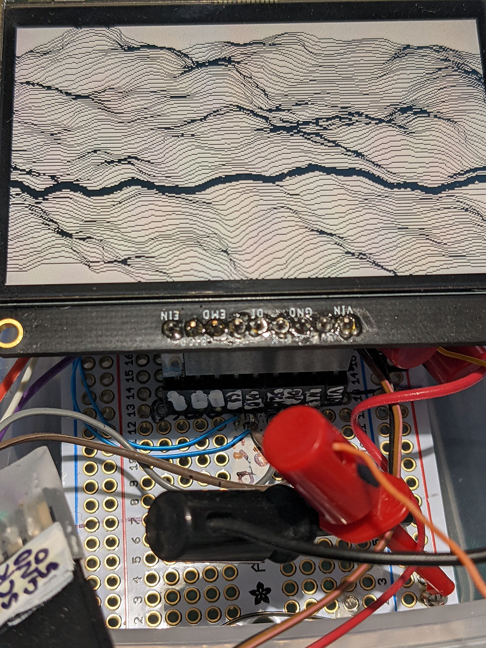
FeatherS2 and TFT Featherwing
I got my 3.5" LCD from Adafruit Adafruit TFT FeatherWing - 3.5 480x320 Touchscreen for Feathers — Little Bird . I tried it on the UM FeatherS2 board and eventually got it going once I worked out which library to use (Arduino_GFX.h and Adafruit_HX8357.h and Adafruit_TSC2007.h) And that SDO was MOSI and SDI is MISO. And that the LDO2 (power regulator for display and gps and stuff) is controlled by GPIO21 on the feather2.
I worked out how to use the ultra-low-power (ULP) micro that is part of the ESP32 -S2 to drive a PWM bit so that I can have the display on even when the main cores are in low-power sleep mode (normal PWM stops then) I programmed it using macro assembler (which brough flashbacks and PTSD from 40 years ago) I could program it in C if I tried hard enough and if I used the Espressive IDE rather than Arduino IDE.
The entire kit pulls about 40mA total (On the 5V USB power) when the cpus are active and the display is on at low-backlight but the GPS is disabled. It jumps up to 80mA when the GPS is also on and trying to get a fix, plus the electronic compass. So far so good.
HOWEVER: The real killer is when I tested it outdoors. In any kind of sunlight I can't see it at all unless I crank the backlight way up to max and then the kit pulls about 200mA when trying to get a GPS fix. Even then visibility isn't great. (Unless I stick it inside my shirt and peer down through my neckline...) Part of this is the eye's response to bright light and part is reflected glare from the screen. If I can block the external light and let my eye adapt, low power usage is feasible. Hmm, need a box with a viewfinder arrangement.... Maybe a folded optical path as well to keep the box small...
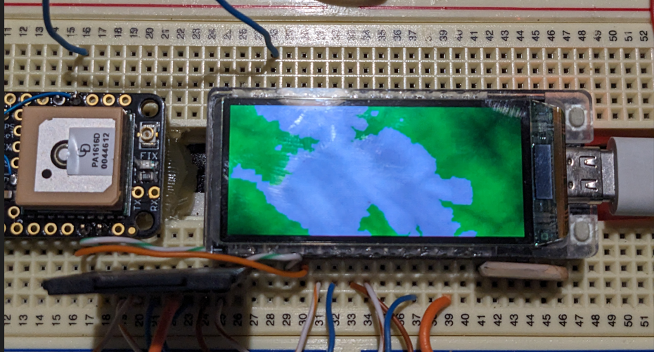
LilyGo esp32_s3 oled
I bought one via LilyGo! T-Display-S3 AMOLED – LILYGO®
Specs
MCUESP32-S3R8 Dual-core LX7 microprocessorWireless
Connectivity2.4 GHz Wi-Fi & Bluetooth5 (LE)
DevelopmentArduino, PlatformIO-IDE, Micropython
Flash16MBPSRAM8MBBat
Voltage DetectionIO04
Onboard functionsBoot (IO00) + Reset + IO21 Button
1.91 inch RM67162 IPS AMOLED:
Resolution 240 X RGB X 536(H)
InterfaceQSPIActive Area19.8*44.22mm
Driver ICRM67162
Viewing AngleIPS Full View Angle
Compatibility
I have seen that this can be used with tft_eSPI, but not through their driver. The methodology was to use another driver (by NikTheFix) that was able to take an tft_eSPI sprite and push it to the display. That driver is available along with example code from TDisplayAmoled/AmoledT-Display/HelloWorldAmoled at main · VolosR/TDisplayAmoled · GitHub
Make for it to go!
I made it all work without too much drama and displayed a terrain height map on it. Quite nice, great res and colors. Visibility in bright light is not great though. Plus it is quite small. Cute though. If I put it in a lightproof box with a magnifying viewer it might work out...