LILYGO T Display AMOLED for GPS
- terrycornall
- Jul 24, 2023
- 32 min read
Updated: Feb 8, 2025
Intro:
In keeping with my search for a platform to build a hiking GPS on that will last for a week in the field without recharging, show me color maps and terrain and tell me where I am, I'm exploring the use of the LilyGO T display S3 with Amoled display. Its display is small but fast, hi-res and glorious color. It's based on an esp32s3 so has power-saving sleep modes plus 2-cores of 240Mhz Tensilica LX7 and wifi and bluetooth. Programmed in Arduino Framework (Or Espressiff or Micropython) with FreeRTOS support. Has battery charge circuit. Has quite a few (18-ish) GPIO pins for extensibility, like UART to GPS, buttons, rotary encoder etc. Display connections are already made so the 18 GPIOs are all free for developer.
This blog is more to remind me about things than it is a detailed recipe for 'how to do it' but it does have some tips that you may find useful.
Credits:
Thanks go to NikTheFix and VolosR for developing and popularising via Youtube an AMOLED driver for this board. Link to their stuff is TDisplayAmoled/AmoledT-Display/HelloWorldAmoled at main · VolosR/TDisplayAmoled · GitHub.
Also, there's a writeup by 3Dsf.info about using the “GFX Library for Arduino” by “Moon On Our Nation” which apparently does support the chip used to control the display. Link here: Mini Displays (google.com)
Datasheets, pinouts, schematics etc

LilyGO, she no GO!
OK, I exaggerate a little, but there are definitely issues.
I bought this lovely little board/display from LilyGO.
T-Display-S3 AMOLED – LILYGO® and I got the updated one with AMOLED display.
Plugged it into USB on my Windows 10 box and LILYGO logo came up on the board's display. Fine so far and looks good (though the smallest font is very tiny!). Whatever code was on it tried to connect to network and naturally failed. Screen then advised that I use ESPTOUCH app to configure.
OK, so far as expected.
But I wanna program it via Arduino/vscode IDEs so I thought to skip the wifi config stage. So I cranked up Arduino IDE and looked for the port that the device was on. Strangely, no serial ports appeared to have any devices (except the omnipresent com1. Gotta find out what I can do with that one day...)
Started Device Manager and looked at Event viewer for devices and by looking to see what disappeared/reappeared when I reset the Lilygo, I worked out that it showed up as a USB composite device with hardware ids as below. But no Com port and no Jtag/serial debug unit. I begin to suspect a driver issue...
Device USB\VID_303A&PID_1001\48:27:E2:EA:4E:28 was started.A bit of scrolling around the interweb didn't reveal anyone else having a similar issue so I wonder if my adventures with Zadig tool and drivers for the similar Unexpected Maker Feather S3 board had upset something... (See https://terrycornall.wixsite.com/website/post/debugging-the-esp32s3-debugger )
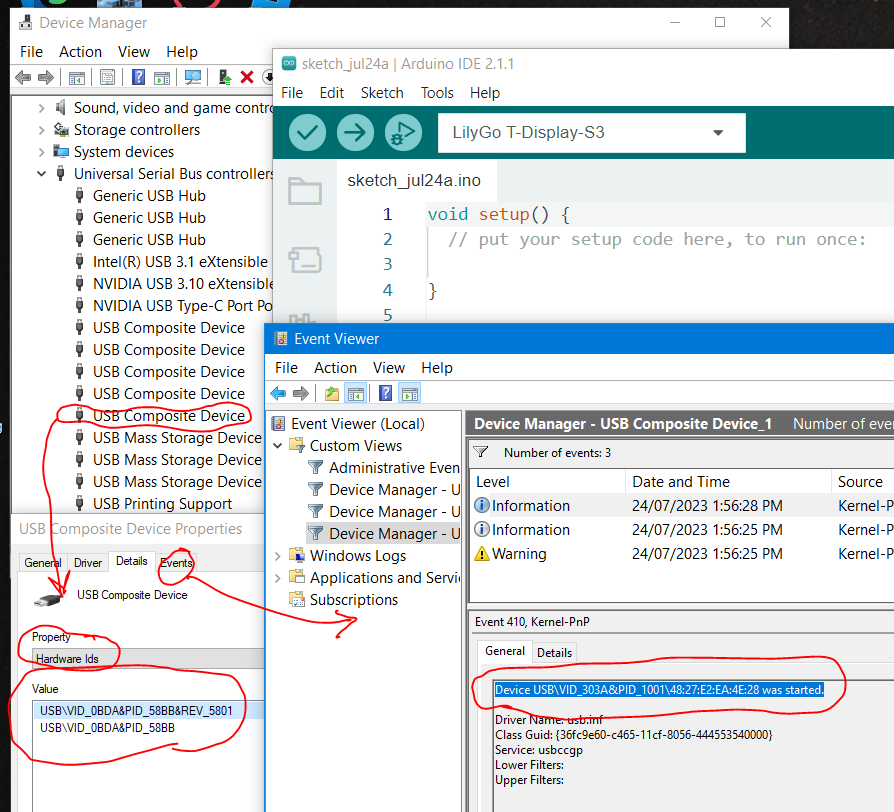
Reading the readme.md at GitHub - Xinyuan-LilyGO/T-Display-S3-AMOLED: An upgraded version of T-Display-S3. I see that I need to do the boot-reset thing, i.e. hold the boot button, press and release reset, release the boot button. I had already done that, screen stays blank (i.e. it's gone into bootload mode) but no difference, can't see any COM port!. Grrrrr.
I also come across this in the readme.md on that github site mentioned above. I've already changed USB cables. So it's probably the USB driver thingy. (Thought so...) I do find this odd though because I have no serial driver issues with another esp32s3 board. Obviously they are not all the same!

So I installed the driver from CP210x USB to UART Bridge VCP Drivers - Silicon Labs (silabs.com) using their instructions and reset the Lilygo and... no COM port.
OK, so I reset the PC and then... Oh, wait, now in Device Manager I see two libusbK USB devices now with two Jtag/serial debug units. Was that there before? Not sure. Anyway, this is similar to the problem I had with the FeatherS3. I might just have to replace the driver for the one on interface0 to make it a Serial device and have a COM port.
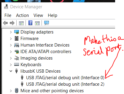
So I chose the interface 0 one and right-clicked and hit Update driver. Follow the pictures from here.


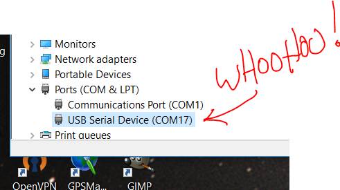
OK, now I see a new serial port and hopefully so will Arduino/vscode IDEs.
I can't help but wonder if I brought this on myself by the use of the Zadig tool, or if I would have had this problem anyway, in which case the fiddling I did with the UM FeatherS3 was invaluable way to learn how to solve the problem...
Next... blinky
OK, Arduino IDE sees that com 17 is available albeit with a strange name, but that's not unusual. I select the esp32->LilyGo T-Display-S3 from the boards list as that is the closest I can find (no mention of AMOLED anywhere...)
Led is on GPIO38 according to the schematic at
so I modded the usual Arduino blinky sketch with a #define LED_BUILTIN 38 and uploaded/downloaded it to the board (after the usual pfaffing with boot-reset and choose the frickin' port again. (BUT WAIT, I just installed Ardu-weeny IDE 2.2.0 and it appears to at least not lose the port all the time. WhooHoo!)) and it blinks. Woopydo.
HelloWorldAmoled
I already know that I need to use a workaround developed by NikTheFix for the display driver, as discussed in TDisplayAmoled/AmoledT-Display/HelloWorldAmoled at main · VolosR/TDisplayAmoled · GitHub
So I got the files from VolosR's github page (including the rm67162.h and .cpp)
and uploaded the HelloWorldAmoled.ino sketch below. Note the use of lcd_PushColors() from rm67162.cpp to push the sprite to the display after doing the drawing to it, rather than drawing directly to the display. (This is the workaround that allows us to use tft_eSPI library even though I think it doesn't support the rm67162 controller chip directly...)
#include "rm67162.h"
#include <TFT_eSPI.h>

TFT_eSPI tft = TFT_eSPI();
TFT_eSprite sprite = TFT_eSprite(&tft);

void setup()
{
  rm67162_init();  // amoled lcd initialization
  lcd_setRotation(1);
  sprite.createSprite(536, 240);
  sprite.setSwapBytes(1);
  draw(); //moved this to setup instead of loop. Why do it more than once?
}

void draw()
{
 sprite.fillSprite(TFT_BLACK);
 sprite.drawString("Hello Wordl",20,20,4);
 sprite.fillRect(10,100,60,60,TFT_RED);
 sprite.fillRect(80,100,60,60,TFT_GREEN);
 sprite.fillRect(150,100,60,60,TFT_BLUE);

 lcd_PushColors(0, 0, 536, 240, (uint16_t*)sprite.getPointer());
}


void loop()
{
  //draw(); //really? Why redraw it all the time? Is now in setup()
}
Works and I see Hello Wordl and some colors. Great!
Power to the ... device
I see it using 50-70mA when just sitting there with about 1/5 of the AMOLED lit up. This seems excessive. It might still be trying to use the wifi and almost certainly is running flat chat at 240Mhz.
I'll turn down the clock using... hmm, how did I do that last time? setCpuFrequencyMhz(uint32_t cpu_freq_mhz);

Hmm, asking for 10MHZ kinda failed. The screen stayed blank.... Same with 40. Wonder if 240 works? Yes, that's OK. Oh, I need to know what crystal it is using. Maybe its 26Mhz or 24Mhz rather than the 40Mhz. in which case 13 or 12 might work
Jeez, I am getting sick of having to reselect the freeking port all the time after a boot-reset!
Anyway, 12 MHz clock worked (must be a 24Mhz crystal) but power is still flicking between 70 and 50mA.
So to turn off the wifi.
  #include  <WiFi.h>
  .......
  WiFi.disconnect(true);  // Disconnect from the network
  WiFi.mode(WIFI_OFF);  //turn it off
  WiFi.setSleep(true);  //sleep just to make sure?
Nope, still using about 50-70mA. What is going on? Is that as good as it gets?
Not happy....
OK display nothing... 50-70mA. Huh. Weird. Wonder if I am really turning off wifi or not. Or maybe my power meter is crap. That the display being black makes little difference is a puzzle too.
I tried a different approach and used lcd_display_off() and that might have reduced draw by 20mA. Shows 50mA now without flicking up to 70.
BTW, to change brightness use lcd_brightness(uint8_t bright)
To turn if on use lcd_display_on()
Also, if I fill the display with white, using lcd_fill(0,0, 536, 240,TFT_WHITE); , current draw goes up to 80mA.
Interestingly though, when sitting in bootmode it's only drawing 10mA. So it is capable of running at a low power. Just have to find out what settings I need to fiddle. And how to.
Soooo, I used this code in the loop to put the board into light sleep mode after drawing once in setup and now my (admittedly poor sensitivity) power meter is showing 0.00 A which means the draw is below 10mA. Display is still showing though and quite nicely at a brightness level of 128. Looks good for low power ops!
Redrawing the display at 1 sec intervals bumps the current to 10mA every now and then.
When I measure the current from the 4.2V-ish battery rather than the 5.2V-ish USB, with a somewhat better meter, I get 17mA, jumping up to 22mA when the chip wakes up and does something. I'm either dismayed that the USB meter is so crappy or pleased that the power down-regulator is so efficient. (I'm betting on the former....) Anyway, I'm in my ballpark for acceptable power usage of 20mA ish.
#include "rm67162.h"
#include <TFT_eSPI.h>
#include <WiFi.h>

TFT_eSPI screen= TFT_eSPI();
TFT_eSprite sprite = TFT_eSprite(&screen);
#define screen_width 536
#define screen_height 240
#define BOOT_BUTTON GPIO_NUM_0
#define USER_BUTTON GPIO_NUM_21
#define USER_LED GPIO_NUM_38

void setup()
{

  pinMode(BOOT_BUTTON, INPUT); //has an external pullup. Probably don't need to set this mode, already is. But completeness...
  gpio_wakeup_enable(BOOT_BUTTON, GPIO_INTR_LOW_LEVEL); //if gpio 0 (boot button) is low, wakeup. This works.
  pinMode(USER_BUTTON, INPUT); //has an external pullup
  //gpio_wakeup_enable(USER_BUTTON, GPIO_INTR_ANYEDGE ); //if gpio 21 (the other button) goes low, wakeup. This (using edges) DOESN'T works.
  gpio_wakeup_enable(USER_BUTTON, GPIO_INTR_LOW_LEVEL ); //if gpio 21 (the other button) is low, wakeup. This (using level) works.

  esp_sleep_enable_timer_wakeup(1000000); //one second in useconds. I can specify this once and be done. No need to do it every time.
  esp_sleep_enable_gpio_wakeup(); //or wakeup earlier if (boot) button on GPIO 0 or user button on gpio21 is pressed
  rm67162_init();  // amoled initialization
  lcd_setRotation(1); //this is a landscape mode with the screen top left being in actual top left when the USB coming is off the rhs.
  sprite.createSprite(screen_width, screen_height);
  sprite.setSwapBytes(1);
  lcd_brightness(128);  //32 is pretty dim and 255 is pretty bright. 128 is fine for indoors. Could go a little lower than 32 if using at night in dark.
  draw(0,40); //

}

void draw(uint16_t x, uint16_t y)
{
 sprite.fillSprite(TFT_BLACK);
 //sprite.drawString("Hello Wordl via AMOLED",20,20,4);
 sprite.fillRect(x,y,60,60,TFT_RED);
 sprite.fillRect(x+60,y,60,60,TFT_GREEN);
 sprite.fillRect(x+120,y,60,60,TFT_BLUE);

 lcd_PushColors(0, 0, 536, 240, (uint16_t*)sprite.getPointer()); //normally you write to screen using sprite
 //lcd_fill(0,0, screen_width, screen_height,TFT_WHITE); //this allows direct write to screen bypassing sprite
}

void loop()
{
  static uint16_t x=0, y=0;
  //nuffin to do, go to sleep. THIS MADE A HUGE DIFFERENCE IN POWER CONSUMPTION. FELL TO below 10mA
  //EVEN THOUGH THE DISPLAY IS STILL ON AT BRIGHTNESS LEVEL 128. WHOOHOO!
  esp_light_sleep_start(); //Will wakeup via timer or button(s) pressed

  x+=5;  //marching the colors
  if (x>screen_width){
    x=0;
    y+=5;
    if (y>screen_height){
      y=40;
    }
  }
  draw(x,y); //draw again  to see what happens to power. Jumps to 10mA every second.
}
BTW, the use of names like lcd_rotation() is not my choice and I know that the AMOLED is not an LCD or a tft. (Bugs me like crazy but I don't want to set up aliases. I'm not quite that OCPD about it.)
Lilygo ESP32s3-T3-Amoled and "Ultimate" GPS Featherwing
I put the LilyGo and the Adafruit gps on a breadboard. Here are the pinouts. From Pinouts | Adafruit Ultimate GPS featherwing | Adafruit Learning System
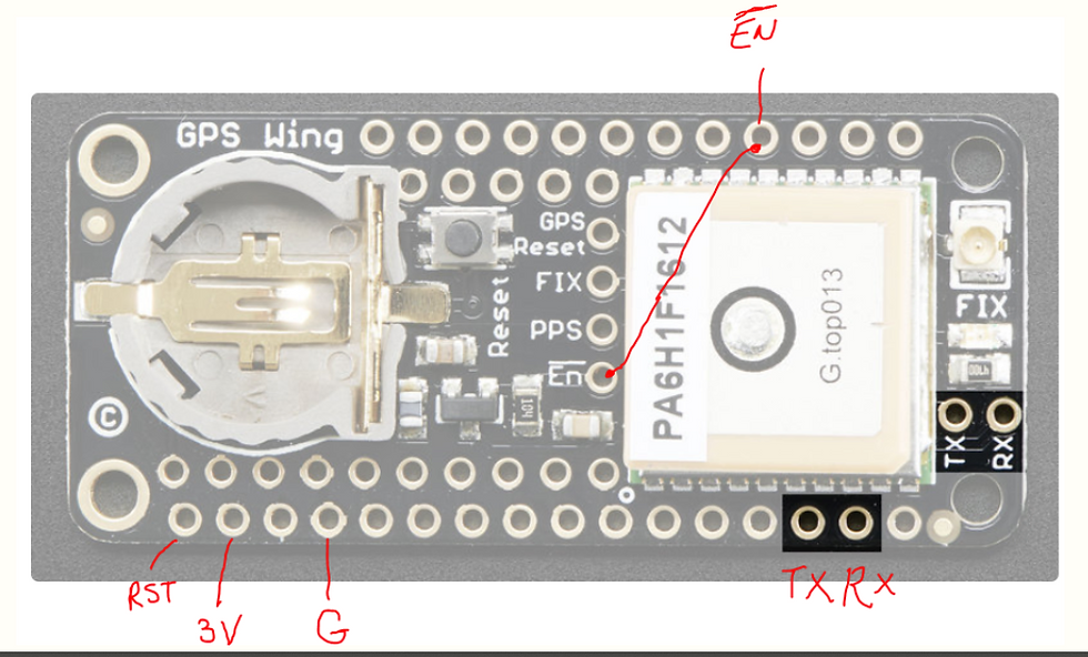
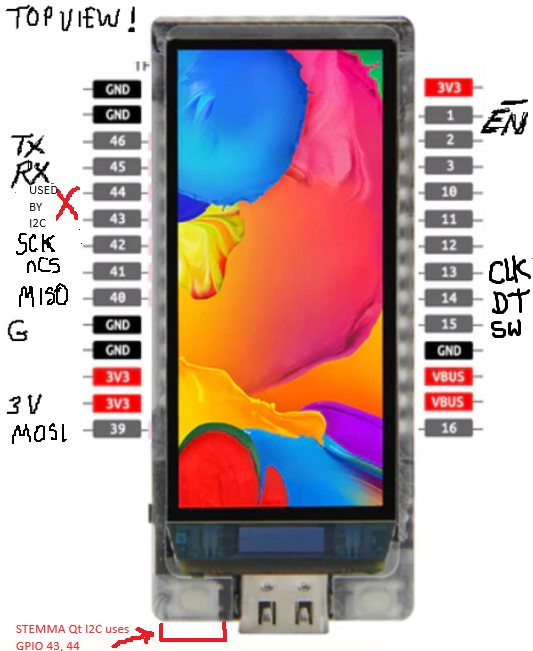
I used uart1 (don't use uart0, I think it's involved in programming. DON'T USE UART2 BECAUSE IT DOESN'T WORK TO WAKEUP esp32S3! (Of course I chose uart2 and fought with it for hours before I came upon that little gem, didn't I...)
TX and RX and uart wakeups on the ESP32S3 board are configured like:
  Serial1.begin(9600, SERIAL_8N1, 45, 46); //(baud, lineformat, RX, TX)
  esp_sleep_enable_uart_wakeup(UART_NUM_1);
  uart_set_wakeup_threshold(UART_NUM_1, 4); //pos edges need to wakeup
Remember that TX of GPS->RX of ESP32S3 ! (and similarly RX<-TX)
Wake Up!
I got the UART to wake the CPU out of light sleep and with a bit of fussing around can now get the $GNRMC strings that the GPS sends once every 10 seconds (after I told it to do that), with some reliability. Had to experiment with some things, like a delay after wakeup before reading the UART receive buffer, how many positive edges to set as the threshold for wake (4 seems optimal) and what that does to the leading chars (I get NRMC instead of $GNRMC). Then how to parse it to extract the time, date, Lat, Lon etc fields and also deal with empty fields. (a bit of code that implements a strtok_single() to overcome strtok()'s annoying habit of treating multiple commas as if they were just a single comma)
esp_sleep_wakeup_cause_t wakeup_reason = esp_sleep_get_wakeup_cause();
switch(wakeup_reason ){
  case ESP_SLEEP_WAKEUP_UART:
    delay(50); //give it time to get message
    n=Serial1.readBytes(dispString, LEN_DISP_STRING);
    if(n>0){
          dispString[n-1]=NULL;
    }else{
          dispString[0]=NULL; //make sure its an empty string
    }

    dispString[LEN_DISP_STRING-1]=NULL;
    sprite.drawString(dispString,0,0,4);
    if(strstr(dispString,"NRMC")==dispString ||
                 (strstr(dispString,"$GNRMC")==dispString )){
//note that strtok() treats multiple delimiters like a single
//whcih is why we need this special function strtok_single()
       char *tok=strtok_single(dispString,",");
       n=1; //line number
       int m=0; //x pos in pixels
       char * tokP=NULL;
       do{
          if(!strlen(tok)) //is tok empty?
             tokP="NODATA"; //substitute * for an empty
           else
              tokP=tok; //otherwise just keep pointing at tok
           sprite.drawString(tokP,m,n*20,4); //show me the tokens
           n++;
           if(n>(screen_height-20)/20){ //wrap around on last line
              m+=200; //x pos in pixels
              n=1;  //line number
           }
        }
        while(tok=strtok_single(NULL,","));//find the next.
        }
        lcd_PushColors(0, 0, screen_width, screen_height, (uint16_t*)sprite.getPointer()); //show me on amoled
        break;
And tok_single() is
//got this from https://www.programminghomeworkshelp.com/c-assignment/ to solve the 'multiple delimiters in a row' problem with strtok()
//for normal case, acts like strtok() but in case of multiple delimiters in a row, returns an empty string, BUT NOT A NULL!
char * strtok_single (char * str, char const * delims)
{
    static char  * src = NULL; // so it remembers the src string from last time if called with NULL as the str
    char  *  p,  * ret = 0;

    if (str != NULL)
        src = str;

    if (src == NULL)
        return NULL;

    if ((p = strpbrk (src, delims)) != NULL) { //finds the first char (delimiter in this case) in the src
        *p  = 0;  //p was pointing to the position of the first delimiter so it just got deleted and turned into a 0 BUT p itself is NOT A NULL POINTER!
        ret = src; //so src now points to the src but with the delimter removed, so it's effectivly returning an empty string, but NOT A NULL
        src = ++p; //and the src for next time is the string one char after the first delimeter was

    } else if (*src) {
        ret = src;
        src = NULL;
    }

    return ret;
}
Sleep the GPS as well.
The next thing to do is disable the GPS whilst CPU is in sleep, using GPIO 01 pulled hi. Does it stay hi when we are in sleep? I think so.. I tried this manually and it does cut down on power by some 40mA. If there is no battery in the GPS, after re-enable it needs to have its parameters reset because it forgets that I told it I wanted 10 sec updates and only GNRMC strings, plus it takes a while to regain the satellites (sometimes as much as a few minutes indoors). With the battery to keep the time and ephemeris data, this isn't needed, though it takes some 10 seconds to lock onto sats and to start spitting out GNRMC messages again, that's kinda expected. I think this will work, but defo needs that battery in the GPS. (Or just connect the 3.3V main battery to where the 3.3V coin cell goes?)
State of Events
Want to use a state machine approach to keep track of things, using wakeup reason as the event. This should work for deep as well as light sleep. I think I can adopt an approach that goes something like: deep sleep with gps and display off until a button is pressed followed by light sleep with gps and display on whilst waiting for a fix followed by light sleep with display on, gps off and a timer that will put it into deep sleep with all off until a button press.
Power on.
Setup wake events, enable GPS, display on, State=WAIT_FIX, go light sleep;
WAIT_FIX:
If Event=WAKE_ON_UART, if got new fix, display on, show new fix, State=WAIT_DISPLAY, disable GPS, go deep sleep for 1 min. If no fix, State stays WAIT_FIX, go sleep for 1 min (or until uart)
WAIT_DISPLAY:
if Event=WAKE_ON_TIMER then disable display, disable GPS, State= WAIT_BUTTON, go deep sleep.
if Event=WAKE_ON_BUTTON then enable display, go light sleep.
WAIT_BUTTON:
If Event=WAKE_ON_BUTTON then State=WAIT_FIX, enable display, display last fix, enable GPS, go light sleep.
'Ultimate' GPS featherwing
Paradoxically, this is the second version of the 'Ultimate' by Adafruit. (The first version should have been the Penultimate!). Is quite a good GPS , smallish, lowish power, has an /EN pin you can use to reduce power down to almost nothing whilst keeping it in a warm-start mode (if you have the battery in). One issue is that it seems to flatten the coin cell battery extraordinarily fast, so I merely connected 3.2v rail to the coin-cell battery-holder positive (having taken the non-rechargeable coin-cell battery out!) and this serves to keep it in warm-start whilst the /EN signal is pulled high (thus disabling GPS and saving power whilst CPU is in sleep). This way the main Lipo battery acts as backup battery to the GPS.
With this GPS and the AMOLED display and a sensible sleep policy I'm getting measurements that point to somewhere between 50 and 100 hours of operation (most of the time in sleep with the display off) but being able to get a new fix within about 10 seconds of demand.
Interestingly, having the display off doesn't seem to make a huge impact on current (I find that hard to believe. It should be pulling at least 10mA). The main things are the CPU in sleep and the GPS disabled. Nonetheless, no point having it on wasting photons if I am not looking at it. EXCEPT in situations like the odd snowstorm when I'd like to see it without fumbling for buttons. Like if I install it behind a Fresnel lens in my ski-goggles or something.
I have found that sending the CPU to deep sleep causes the GPS to go enabled again, because of the 100K pulldown resistor R2. So I propose 'tombstoning' the resistor and connecting a wire to 3.3V instead of GND. Either that or remove it and wire in a 100K pullup resistor using some of the prototyping area. Also, since the battery is out of circuit and I don't need the battery holder, I might take the battery holder off the board and replace it with a microSD card holder, which I need for map data.
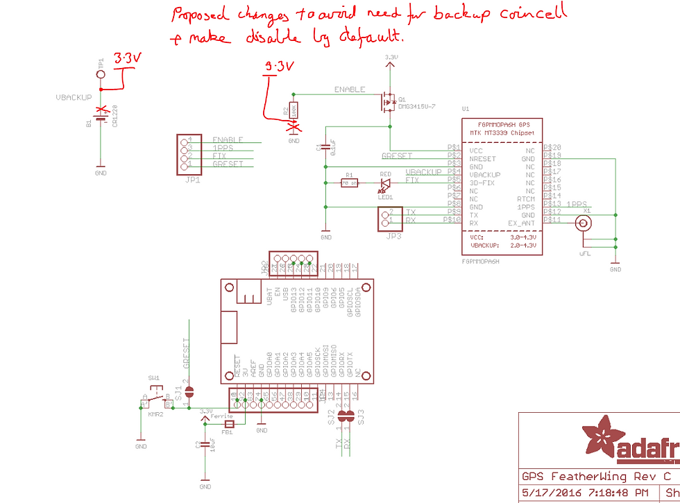
I had to try a few things, putting in delays during the GPS setup, before I do a disable_gps(). Get it wrong and the gps setup doesn't take. I had to be careful during trials with repeated reflashing of the target CPU board that I tested code behaviour from the GPS being completely off (unpowered or press GPS's reset button WHEN IT IS NOT DISABLED) because otherwise it can remember its configuration from a past attempt, making debugging tricky, not knowing if its behaviour is due to previous attempts or this code cycle. Many times I thought I had it right only to discover that when I power-cycled it didn't work properly. Not only that, but sometimes it did and sometimes it didn't. And once I saw it get stuck in a non-responsive mode that wouldn't do anything and I thought I'd bricked it. (Turned out I just had to make sure GPS was not being held disabled when I tried to reset/power-cycle it.) Note the use of delay() not sleep_delay() (which is a function I wrote that uses light_sleep). This is because light_sleep pauses the UART tx, and even with the use of flush() there are still a couple of bytes left in the 'breech' (UART TX buffer) so sleep messes with them.
#include <Adafruit_GPS.h>
.....
setup(){
.....
Serial1.begin(9600, SERIAL_8N1, 45, 46);  //specify rx,tx pins
enable_gps();
GPS.begin(9600);
sleep_delay(500); //is this really needed? Yup. 100 is too small
GPS.sendCommand(PMTK_SET_NMEA_OUTPUT_RMCONLY);
delay(5); //is this really needed? Yup. Maybe can be smaller
GPS.sendCommand(PMTK_SET_NMEA_UPDATE_10Sec);
Serial1.flush(); //make sure all sent (but don't forget the two in TX buffer)
delay(10); //so wait a bit more to let the gps digest commands
disable_gps(); //keep it off until we need it
......
}
Have decided that UART to GPS is a pain and will look for one with an SPI interface to replace it.
SD card needed
I need a micro-sd card holder for map and terrain data. There's room under the GPS board for one, and a bit of prototyping space on the GPS board. If I remove the battery holder and hard-wire it to 3.2V I'd have even more room. As discussed above, the GPS backup battery doesn't seem to work particularly well (eats batteries) and might as well be replaced by a direct connection to 3.3v. (If I remove the VBACKUP completely, I lose the ephemeris every time I put the GPS into disabled state so it does a cold-start every time which is less than ideal although it re-connects pretty fast anyway)
Then I'd need an SPI interface to the micro-sd. I have previously figured out that the adapters you can get (and I seem to accumulated tons of them) that make a micro-sd card fit into a larger (old) SD card slot can be easily adapted to a microcontroller. All the circuitry, spi peripheral controller etc is on the actual micro-sd card so all you need is access to the pins. Now, you could solder directly to the micro-sd but that'd make it hard to stick it in a reader. So instead, solder to the adapter pins, wire it up to your microcontroller and then stick the micro-sd into the adapter. Easy-peasy. This is the pinout of the adapter, with SPI terminology, that I copied from the interweb, Visio-SDPINOUT.vsd (tayloredge.com) remember, VDD is 3.3V max as are the signals so if you are using a 3.2V micro as I am, no level shifters are needed.
If the width of the adapter is a pain, you can cut it down the sides a bit as the two outside pins aren't needed. Then melt the plastic closed again. Or take out the internal pins and make your own surround would allow you to make it even smaller. Or stop being cheap and go buy a purpose made micro-sd add-on module.
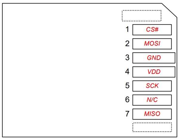
There's also an article on Cheap DIY SD Card Breadboard Socket : 8 Steps - Instructables to build an adapter that the larger SD cards (I have a few of those around too. Hmmm) can slide into and out of, using just a bent-over pin header strip. Neat. Maybe too chonky and not secure enough for me, but neat.
See the image above in the GPS section for which pins I use for the SD card.
Sad SD Software
Maybe it's just me, but I seem to have a lot of issues with SPI busses and SD cards. I finally got the SD working once I tried a different way of declaring the SPIClass using SPIClass sdspi(HSPI) rather than SPIClass sdspi = SPIClass(HDSPI) which I had used in a previous project quite happily. One difference is that the previous project encapsulated the sdspi as a class member and in this project, so far, sdspi is just a global variable. Why that should make a difference, or if it does, or if it is the difference between esp32s3 and esp32s2, I dunno. Anyway, this works:
#include <SD.h>
......other includes

//SPI bus pins
#define SD_MISO 44
#define SD_SCK 43
#define SD_MOSI 42
#define SD_nCS 41

SPIClass sdspi(HSPI); //NOTE: Don't use SPIClass sdspi = SPIClass(HSPI)
//although this DID work as a class member for the esp32s2 !??!

bool sd_ok = false;
....other globals

void setup()
{
 ...other setup
  //Setup SD card SPI interface
  sdspi.begin(SD_SCK, SD_MISO, SD_MOSI, SD_nCS); //SCLK, MISO, MOSI, nCS
  if(!SD.begin(SD_nCS, sdspi)){ //connect the SD card to this SPI bus
  //wa-wa-wahwah
    sd_ok = false;
  }else{
    sd_ok = true; //WooHoo! got it.
  }
 .....other setup, loop() etc.....
Show me the map
So, I tried to use the mapping software I developed for the LCD enabled esp32s2 previously to display terrain. It compiled and ran OK, but the terrain display is all corrupted. I'll have to look through the code to see if there is any eggregious mistakes like assumed screen size or similar. (I got it to work. Read on)
PSRAM not enabled?
One thing I thought of, is there enough memory? Should be but, is the PSRAM (8M of it) actually enabled?
I (thought) I found that the PSRAM (of which it has 8MB) is not enabled by default. Also that there is no corresponding line in the LilyGo T-Display-S3 board definition to allow you to enable it!
The code that made me think it wasn't enabled is like:
Serial.begin(9600)
delay(10000); //Give me achance to manually reconnect
Serial.println("Hello AMOLED");
#ifndef BOARD_HAS_PSRAM
Serial.println("PSRAM not enabled");
#endif
Which did return:
PSRAM not enabledHowever, fiddling around with the boards.txt in C:\Users\terry\AppData\Local\Arduino15\packages\esp32\hardware\esp32\2.0.11 made me wonder if maybe the PSRAM is actually compiled in and it's just that the BOARD_HAS_PSRAM isn't defined (there's no PSRAM setting in the menu)
I guess if it isn't then efforts to use a big chunk of mem will fail.
I could check the amount of free heap memory... but I don't think that reflects the PSRAM. Ah, found something at this website... Use PSRAM (upesy.com)
#include <esp.h>
....
  int FreePsram = ESP.getFreePsram();
  Serial.printf("before demap.begin %d FreePsram \n", FreePsram);

  //to hold terrain we use a deMap class

  demap.begin(&screen, "/gwinear_255.bin", "/gwinear_bounds.jsn"); //open a digital elevation map and draw it to its sprite
  FreePsram = ESP.getFreePsram();
Resulting in:
before demap.begin 8085743 FreePsram
Size of boundsDoc=288
Read jsonfile OK  name=Mt St Gwinear minAlt=700, maxAlt=1550, demWidth=373, demHeight=213
Deserialization of jsonfile for bounds OK
zoom=0.857909 minMapScale=0
after demap.begin 7699055 FreePsram
Sounds like it's all there and my deMap class is using 8085743 - 7699055 = 386688 of it. That sounds right for this screen size. It amounts to 536x240x3 byte chunk of mem (why x3 and not x2? I thought we were using rgb565 which is 2 bytes per pixel, not rgb which is 3 bytes.)
Ah, I know. The BLOCKRAM stores 8 bit altitude values and there is also a sprite in the demMap class that stores 16 bit pixels, so that's why the x3.
Have to use ps_malloc() rather than malloc() to get it. Interestingly , if my explanation for the x3 memory usage above is correct, it looks like the deMap's sprite's memory is allocated from the PSRAM as well without me having to do anything explicit about it.
However, see below in the section called "Lost my memory" because at a later time the PSRAM went disabled (probably a software update) and I had to mod the boards.txt to fix that.
Terrain display
Still not looking good. It draws 'something' but it isn't what I expect.
OK, fixed it. I was using a pointer to the sprite where I should have been using a pointer to the sprite's image memory. Silly me. Image is still 'ripped' but colors look better. Some screen/sprite dimension clash going on.
Got it. I assumed the DEM sprite was same size as the screen. It isn't. The dimensions are given by the data file, gwinear_bounds.jsn or similar.
Now it looks better but has a chunk taken out of the middle for some daft reason. Am I drawing a black strip there?. Sigh, more rabbitholing required...
OK, it looks like it is the zoom factor causing issues. Previously it was greater than one and now it is less at 0.8 and I think that the original code can't cope with that. Also, I have code to allow rotating the terrain viewing angle and I think it is showing cracks with the different screen res I am now using. Nonetheless, I see the terrain and it looks OK even on this tiny screen. Valleys and peaks are clear-ishly discernible. (A side view might be better and a rotatable one would be even better-er.

Eat Me!
I did some simplistic current tests (measuring current from USB with battery switched off so not charging) to see what is eating the battery. With a light_sleep versus a spinning CPU (at 240Mhz) delay, with display on, with GPS on or off. These are the contributions.
GPS | CPU (240 MHz) | Display (half brightness) |
45mA | 30mA | 10-30 mA |
I'll test again at a lower CPU clock speed sometime. For now I think I'll rely on the high clock to get things done quickly and then go back to sleep. A big battery_saving thing will be to keep the GPS and display and CPU off when not actually needed so I'll need a good button/timer interface to the user to sleep things when the user isn't actually interested in seeing them, but a quick means of enabling and acquiring when they are. Plus a background timed GPS acquisition without display to keep position known with a reasonable latency (10 mins?) so that the next time the user pokes it, the display can show approximately where they are whilst doing a new acquisition. (I think I want a new position every time the user pokes it.... not sure. Maybe a programmable option?)
Also display brightness will be something to consider. At even only half brightness it is plenty bright (prob too bright for night-time) but in full sun it'll probably need full brightness.
Round and round we go...
I've wondered at the utility of a rotary encoder as a user interface for use when wearing big, boofy, thick, warm, waterproof gloves, as you do, in the snow. So I got a couple of encoders from Jaycar. XC3736 User Guide (jaycar.com.au) and Rotary Encoder Switch with Pushbutton SR1230 | Jaycar Electronics
The XC3736 operation looks pretty simple. One falling edge on the clk signals a change and if clk == dt then you are rotating one way and if != then you are rotating the other way. It has detents and feel like about 20 clicks per rotation. It also features a pushbutton as well as the rotary encoder (press down on the shaft) It comes on a little pcb with a header and 10K pullup resistors. No knob. I had to 3d print one.
The SR1230 costs $10 (twice as much as the XC3736) and doesn't come on a circuitboard with pins or pullups. It has more clicks per rotation, about 30, BUT unlike the XC3736 it has 2 detents per cycle so the coding would need to be slightly different. The detents feel more positive and it is harder to leave the encoder on a non-detent position. Otherwise it operates the same way, once you identify which pin is which. (Look at that website, it has the manual)
These switches are not really big, but they aren't tiny either. Plus how do I waterproof them? Hmm. Maybe an o-ring on the shaft? Grease-filled gland?
For the fact that the XC3736 already has its little pcb and pullups and costs half as much, I think that'll be the way to go. 20 clicks per rev is plenty. (I might have changed my mind. I like the positive feel of the SR1230. Honestly, either will do.)

See pins in the GPS section for what pins I use on the LilyGO to interface to the rotary encoder. (Note clk,dt on XC3736 is same as A,B on SR1230)
I want to setup ROT_CLK as an interrupt and also as a wakeup pin. How do I do that? There is a complication wherein if the switch is already at the wakeup level, esp_light_sleep doeesn't happen so I set it to opposite. Like this:
....
//handler for rotary encoder interrupt. Also gets called when the //attached signal causes a wakeup
//the IRAM_ATTR keeps the code in RAM so it runs faster.
void IRAM_ATTR rotary_encoder_clk(){
  toggle_led();
}

...somewhere in the code. I choose to do it dynamically just before esp_light_sleep() so I can see what the switch level currently is and set the wakeup and interrupt to the opposite
...
rot_sw=digitalRead(ROT_SW);
  if(rot_sw){ //what is the GPIO level?
    //  if it's high, then wake me when it goes low
    gpio_wakeup_enable(ROT_SW, GPIO_INTR_LOW_LEVEL );
    rot_sw_wakelevel = false;
    attachInterrupt(digitalPinToInterrupt(ROT_SW), rotary_encoder_sw, FALLING);
  }else{
  //if it's already low then wake me when it goes high
    gpio_wakeup_enable(ROT_SW, GPIO_INTR_HIGH_LEVEL );
    rot_sw_wakelevel = true;
    attachInterrupt(digitalPinToInterrupt(ROT_SW), rotary_encoder_sw, RISING);
  }
....
bool res=esp_light_sleep_start(); //won't sleep if already at wakeup
                                    //level
There are a number of issues.
FALLING as a mode won't work for wakeups but does work for interrupts. This means that can't use an edge to wake it and if it is already at the wakeup level the CPU won't go into sleep mode.
Can use the same signal for both
Interrupts are ignored when in light_sleep state
After adding this (and similar code for another signal), small changes to the code may cause it not to run. Instead it repeatedly tries to boot. Not crash when it gets to a section of code, just not run from the outset. Changing almost anything removes that behaviour but it might come back next time you change something small. WTF? I'll bet it's some compiler optimisation bullshit.
Debounce required
ROT_CLK (and any other gpio pin connected to a wakeup) can and does stay low sometimes. This stops the CPU from going into light_sleep. Maybe can handle by changing the level that does the wakeup to whatever it currently isn't before sleeping. Like this:
level=digitalRead(ROT_SW);
if (level)
    gpio_wakeup_enable(ROT_SW, GPIO_INTR_LOW_LEVEL );
else
    gpio_wakeup_enable(ROT_SW, GPIO_INTR_HIGH_LEVEL );
esp_light_sleep_start();
Don't count on easily achieving "one click of the rotary encoder advances one menu item" when using the rotary encoder to also wakeup. I think that sometimes it might miss. It might depend on the debouncing and it might depend on that tricksy little bit of code just above trying to get around the 'switch is already at wakeup level' problem.
Something in the state machine to handle the user-clickery wakeups. The code spends most of its time asleep so does need wakeups on the rotary encoder. It also needs to handle (or ignore) such input for state changes it might cause. i.e. in some states, such as waiting for a message from the GPS, it might not be useful to deal with user-clickery. On the other hand, maybe user-clickery is more important and the uart handling ought to be background. Hmmm.
A really big one is that the code crashes out if one of the interrupt switches (ROT_SW or ROT_CLK) is held active for more than about 1 second when the cpu is in light sleep. Is some watchdoggie getting triggered? Dunno. In the end I found that if I re-attach the interrupts before sleep, the problem goes away. And it doesn't appear to matter which edge FALLING or RISING you use. Wierd....
bool light_sleep(){
.....
if(digitalRead(ROT_CLK)){
    gpio_wakeup_enable(ROT_CLK, GPIO_INTR_LOW_LEVEL ); //
    attachInterrupt(digitalPinToInterrupt(ROT_CLK), rotary_encoder_clk, FALLING); //this stops it crashing if ROT_CLK is held low too long
  }else{
    gpio_wakeup_enable(ROT_CLK, GPIO_INTR_HIGH_LEVEL );
    attachInterrupt(digitalPinToInterrupt(ROT_CLK), rotary_encoder_clk, FALLING);

  }
  bool res=esp_light_sleep_start();
  return(res); //returns true if it slept and false if it didn't
Bouncy bouncy
I've come across the idea that the fixed phase relationship between clk and dt (or A,B) on the encoder allows for a debounceless strategy to detect motion if you consider all the intermediate states in a full cycle (detent to detent). MP Electronic Devices: Yet another algorithm for rotary encoder control (pinteric.com) (includes code)
Considering the two bits clk and dt represented as 11 for neutral, 01 as clk low and dt hi etc, the transitions that represent movement are are 11 → 01 → 00 → 10 → 11 for clockwise and counterclockwise rotation is represented by the chain of states 11 → 10 → 00 → 01 → 11. (Blue or green lines in the diagram below from the paper) Switch bounce or chatter happens on the switch (clk or dt) that last changed and causes transitions back and forth in states. i.e. would represent motion of cw, ccw, cw, ccw, cw..... until the switch settles and the motion was either cw or ccw. Given increments and decrements on each transition these chattering transitions should thus cancel out. "Impossible" transitions involve both clk and dt changing at the same time. This can happen of course but isn't supposed to. The red lines in the diagram below from the paper indicate these.
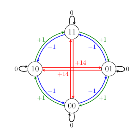
The heart of the code is to add or subtract a count on the basis of transitions in green or blue and so a full rotation (from 11->->->->11) would sum to +/- 4 and switch bounces would add and then subtract 1 (thus cancelling themselves out) until the switches settle, resulting in +4 for a cw cycle and -4 for a ccw cycle. Here's the interrupt routine (slightly modified) from that paper
void IRAM_ATTR rotary_encoder_isr(){
  static unsigned long last_interrupt_time = 0;
  static uint8_t history = 0x03; //state starts at b000011 in detent
  bool rot_clk, rot_dt;
  static int8_t TRANS[] = {0,-1,1,14,1,0,14,-1,-1,14,0,1,14,1,-1,0}; //lookup table to see what to add for a transition. The +/-14 is for impossible trans 0 is for non-transition glitches like 1111->1111
  static int lrsum = 0;
  unsigned long interrupt_time = millis();
  rot_dt = digitalRead(ROT_DT);
  rot_clk = digitalRead(ROT_CLK);
  uint8_t state = 2*rot_clk + rot_dt; //make a 3 bit state value
  history = ((history & B00000011)<<2) + state; //keep last two states in a shift register with most recent state at lsbits NOTE: need those brackets!!!!

  lrsum += TRANS[history]; //add in the value for this state transition to the sum
  /* encoder not in the neutral state, i.e. not finished a cycle yet*/
  if(lrsum % 4 == 0){ /* encoder in the neutral state (on detent). We have finished a cycle */
    if (lrsum == 4){  //cw
      rot_cnt++;      //rot_cnt is a global defined in header
    }else if (lrsum == -4){  //ccw
      rot_cnt--;
    }else{     /* lrsum > 0 if the impossible transition */
      toggle_led(); //show me. This does happen surprisingly often....
    }
    lrsum = 0; //start the cycle again.
  }else{}  //haven't finished a cycle yet, keep on truckin'
  last_interrupt_time = interrupt_time;  //don't use it but might
}
The code represents the state transitions in a shifted-left modulo 4 calculation (lrmem) that retains a binary concatenation of just the last two states and then uses that to look up the appropriate inc/dec/0/impossible value to add to the cycle value (lrsum) from the table TRANS[].
14 is used as the value for an impossible transition because it allows impossible to be recognised in a way that still allows full cycles to be recognised as well. The author says:
Special care must be taken with "impossible" transitions. Due to technical inadequacies, they are indeed possible. If we assign the value 0 to the impossible transitions, the aggregate of a full cycle with exactly one impossible transition is −6, −2, +2 or +6. To recognise that the full cycle contained one (or more) impossible transitions, we must assign a number larger than 10 to the impossible transitions, so that the aggregate of the full cycle will be larger than 4. However, if we assign the number 14, we not only recognise the existence of the impossible transition(s), but also the modulo of the aggregate and 4 is zero again when and only when the neutral state is reached.
Note that the feel of operation depends on which rotary encoder is used. The SR1230 has two clicks per cycle and the XC3736 has one.
clk,dt (A,B) | 11 | 01 | 00 | 10 | 11 |
SR1230 | click | | click | | click |
XC3736 | click | | | | click |
Theoretically you could code a smaller state machine to get more states cycles per rev with the SR1230. However, I found that the '2 clicks per cycle' feels OK. (as does one per cycle) so either is usable with the same code.
The code above (which is my take on the code presented in that paper) does work but probably because of wake-from-sleep/interrupt/other-code misses 'clicks' every now and then. Not perfect but pretty good.
Interrupted sleep
I have found that both wake-from-light-sleep and interrupt appear to work with the same pin. i.e. if it is light_sleeping and a pin wakes it with a falling edge, the interrupt also sees that edge. Neat.
Lost my memory
Not me personally (though sometimes...) but suddenly esp.getFreePSRAM is reporting 0 and naturally my code isn't happy about it.
This came about because I was using the board definition of LilyGo T-display-s3 in the Arduuino boards.txtx (selected under tools in the IDE) but it is incomplete and doesn't have settings for the PSRAM. I was editing boards.txt to put them in but every time that file gets updated I had to re-edit it and I got sick of waiting for them to fix the settings for that board.
A better way is to choose the esp32s3 Dev Board which has more complete settings menu and then enable the OPI PSRAM in the tools menu of the IDE. Also choose a partition sizing to suit 16MB flash. Also turn on the internal jtag for debugging. (I have to try that and see if it works in the Ardu-weenie IDE now...)
What's on the menu?
Ever since I spent ten minutes in a blizzard trying to get to a point in the menus on an early GPS that would allow me to backtrack, and failing, I have nurtured a hatred for context-sensitive menus. I solved it later, after my hands had thawed out in the safety of the hut that I finally reached by virtue of abandoning the use of the GPS and tracing back my easily followed footsteps (but it could have been otherwise). The "back-track" item didn't show up on the "navigation" menu unless you arrived there by one particular trajectory thru the higher menus. To my mind, this is as pointless, stupid and as unsafe as hiding the huts and shelters that should always show on the map, until you are on the lowest possible zoom level. (not bitter...)
So this begs the question of how I should organise the menus of my own device.
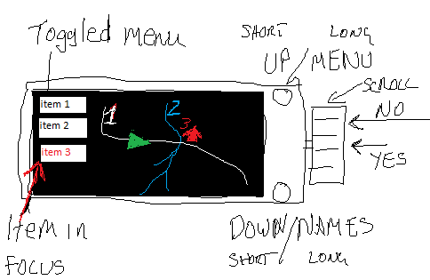
Two buttons. One means "UP" and one means "DOWN" that go up and down the menu pages. One rotary encoder/scroll wheel that scrolls up and down (with wrapping) thru each menu page, one push button on the encoder that can sense a short or a long press. Short press means "use this" and long press means "Don't use this"
Given that the map will show numbers rather than names, I need a quick way to switch between names and map. (Unless I actually adopt the use of the e-paper display for the names) I can do that with a long press on the BOOT_BUTTON
Also I need to set zoom levels. I'd like to do that with the scroll wheel. This shouldn't be a menu item, it should be a function of any display mode. i.e. if showing a map and no menu, moving the scroll wheel should zoom in or out.
The menu for a particular map mode should be toggle-able over the side of the map and easily activated, de-activated. I can use a long/short click on the USER_BUTTON to do that.
Show me the way to go home. LIS 3MDL Magnetometer
I bought a lis3mdl 3-axis magnetometer from Adafruit. Datasheet for the module at Adafruit Triple-axis Magnetometer - LIS3MDL [STEMMA QT / Qwiic] : ID 4479
Datasheet for the device at Digital output magnetic sensor: ultra-low-power, high-performance 3-axis magnetometer (st.com)
It uses the following libraries:
I need to match the I2C signals it uses to the Stemma connector on the LilyG0.
I'm using the Stemma connector to power and communicate with it. That involves GPIO 43 and 44. NOTE: On the LilyGO pin 43 and 44 are brought out on the Stemma QT connector AND on the GPIO headers I initially unfortunately chose tho use 43 and 44 for the SD card SPI but and then tried to use them again for the lis3mdl magnetometer and this was always going to end badly... I used pins
It bothers me that the example code in the Adafruit_lis3mdl Arduino library gives SPI pinouts...
OK, I got over that issue. It can be connected to SPI or I2C but I want I2C so I can use the Stemma QT connectors on it.
Here's code for the I2C connection to the lis3mdl. It kinda works. (read the notes about soft reset after the code)
#include <Wire.h> //note that the class is called TwoWire not Wire...
#include <Adafruit_LIS3MDL.h>
#include <Adafruit_Sensor.h>
Adafruit_LIS3MDL lis3mdl; //magnetometer
//I'm using the Stemma I2C connector, not the SPI.
#define LIS3MDL_SDA 43 //SDA
#define LIS3MDL_SCL 44 //SCL
#define LIS3MDL_I2C_ADDR 0x1C //0x1E 0x1C unless use jumper for 1E
....
Wire.setPins(LIS3MDL_SDA, LIS3MDL_SCL); //init the 'I2C using the I2C pins that the Stemma connector uses
Wire.begin(); //not needed but doesn't hurt
if(!lis3mdl.begin_I2C(LIS3MDL_I2C_ADDR, &Wire)){ //init
mag_ok = false;
esp_restart(); //software reset. This BTW DOES sometimeshelp.
} else{
lis3mdl.setPerformanceMode(LIS3MDL_LOWPOWERMODE); //use least power
lis3mdl.setOperationMode(LIS3MDL_CONTINUOUSMODE);
lis3mdl.setDataRate(LIS3MDL_DATARATE_155_HZ);//slowest most precise
lis3mdl.setRange(LIS3MDL_RANGE_4_GAUSS); // most sensitive range
lis3mdl.read(); //get the magnetometer reading. Uncalibrated so far
//results in lis3mdl.x_gauss .y_gauss and .z_gauss
mag_ok = true;
}
However, on a soft reset (i.e. just reset the Lilygo and not the lis3mdl) , the lis3mdl.begin_I2C() can take more than 10s to initialise, and I'm sure it is not right even then because the magnetic readings don't change even if the module is reoriented and they report the X component as 2.3 Gauss which is too high anyway. (<.65 expected) For a proper power-cycle reset, it initialises very quickly and readings are in range and vary with re-orientation. Power-cyclingthe LilyGo and the lis3mdl before doing lis3mdl.begin_I2C() seems to be the most reliable way. BUT experiments with taking the power off the lis3mdl module and putting it back just before trying to connect to it after a reset of the LilyGO DID NOT RESOLVE THE PROBLEM (and worse, I broke it's AP2112 3.3v LDO regulator) so it appears that I broke the Magnetometer for no good reason and that the fault may well be with the LilyGO after all... and possibly resolvable with software? Maybe?
BTW, au.mouser.com appears to have AP2112K regulators for really cheap and single quantities. However, I can fix it just by soldering its input pin (1) to its output (5) as the volts are already regulated.
So anyway, I bridged around the regulator on the LIS3MDL.
Then after confirming that it still worked (at least when I power-cycle everything) I added code to see if sda or scl were being held low by the LIS3MDL. I found that they weren't after a power-cycle nor after a soft reset, so that's not the issue.
I managed to read the id register at 0x0f, expecting 0x3d returned and got it, even after the soft-reset. Hmm. So it looks like it works just takes a long time to read mags and they are wrong. (after a soft reset but fast and ok-ish after a power-cycle)
Code to read who_am_i register:
  Wire.beginTransmission(LIS3MDL_I2C_ADDR);
  Wire.write(0x0f); //select the whoami register
  uint8_t error = Wire.endTransmission(false); // error will be false
                                          //if we got an ack

  if(!error){
    uint8_t dev_id;
    Wire.requestFrom((int)LIS3MDL_I2C_ADDR, 1, 1); //read 1 and
                                                  //sendStop
    if(Wire.available()){                               //
      dev_id=Wire.read();   // get ID. Expect 3d and do get it
    }
....
Finally I twigged that I was using gpio 43 and 44 for both the SPI and the I2C. Duh! These signals are brought out on both the GPIO headers down the side and on the Stemma QT connector. It never occurred to me that this would be the case.... so when I finally realised it I reassigned the SPI signals I was using to other unused pins, put some blutac over the breadbord pins 43, 44 so I would try to use them again, and all was well. Almost. I found that I had to set the configuration of the LIS3MDL in a particular order or else it always ended up in highperformancemode.
  //DO it in this order or LIS3MDL_LOWPOWERMODE doesn't get set

    lis3mdl.setOperationMode(LIS3MDL_CONTINUOUSMODE);
    lis3mdl.setDataRate(LIS3MDL_DATARATE_155_HZ);//slowest most precise
    lis3mdl.setRange(LIS3MDL_RANGE_4_GAUSS); //most sensitive range
    lis3mdl.setPerformanceMode(LIS3MDL_LOWPOWERMODE); //set power
    lis3mdl.setIntThreshold(500);
    lis3mdl.configInterrupt(false, false, false, // disable all axes
                          true, // polarity
                          false, // don't latch
                          false); // disabled  //global interrupt?
    int mag_perf_mode = lis3mdl.getPerformanceMode(); //chk settings
    int mag_op_mode = lis3mdl.getOperationMode();
    int mag_data_rate = lis3mdl.getDataRate();
    int mag_range = lis3mdl.getRange();
BTW, I have since bought a MUCH better 9 degree of freedom board. (IMU + compass) The BN0085 breakout board from Adafruit. Lovely I2C thing, that does sensor fusion and Kalman filtering and uses quaternions and stuff. Works very well and in one mode gives compass heading corrected for orientation. Note, not the BN0055 though it is very similar hardware but the software on it is different. It might work just as well.


